
The FT290R was introduced in 1981 and proved extremely popular as a portable 2 Metre multimode transceiver. It was replaced by the FT290R Mk2 in 1986 (See separate article). The rig originally provided the then-standard 1750Hz tone burst for opening repeaters. The tone generator was built onto the main PCB and was accessed by pressing the ‘Call’ button which momentarily switched the rig into transmit also.
This article describes the installation of an excellent CTCSS module designed and built by Colin Tuckley G8TMV in a fellow club member’s 290. The installation includes audible annunciation of the tone in use in Morse code, which is particularly useful as the rig’s owner is a white-stick operator. The CTCSS tone is selected from the front panel using the repurposed ‘Call’ button, and the board is powered and switched so that the CTCSS tones are generated only in FM mode on transmit and only when repeater shifts+ or – are selected. If CTCSS were needed in simplex mode, eg. for Echolink, the switching would need to be modified.
G8TMV has recently redesigned his board resulting in a smaller footprint (30mm x 35mm) and only 5mm in depth. This is fortunate as the new board is just small enough to squeeze between the control board and the keypad board (with suitable insulation). There is very little spare space in the rig otherwise, unless the battery container space is sacrificed.
The CTCSS board is supplied with 6.8 volts derived from the FM 6.8v terminal on the regulator board. Reference to the circuit diagram reveals that repeater shifts (either +ve or -ve), are selected by grounding one of two lines via S3c. Isolating diodes are therefore connected to each of these lines to ground the input (LED) side of an opto isolator only in repeater mode. The output side of the opto isolator is wired in series with the 6.8 volt supply, resulting in CTCSS operation only in repeater mode. This is very similar to the method already described for the Icom IC290D. The board is activated by grounding the PTT line, which is straightforward, as the 290’s PTT line is grounded on transmit.

- The tone selection is made by grounding the control line (labelled ‘But’ on the G8TMV board). The Yaesu circuit diagram (below) shows the front panel ‘Call’ button grounding the ‘T Call’ line. It was decided to redesignate this switch as a tone select control as the T Call (toneburst) function is now redundant. Significant angst was caused by the finding that the Call button did not, in fact, connect to ground. Eventually I discovered that the switch consists of two metallic terminals which are ‘shorted’ by a conductive rubber disc resulting in an ‘on’ resistance of around 100 Ohms. Fortunately, this resistance is sufficiently low as to reliably pull the control line ‘low’ enabling tone selection to function as intended. One end of R4003 is lifted from the PCB and the vacated hole is used to connect the’Call’ button to the G8TMV board
-
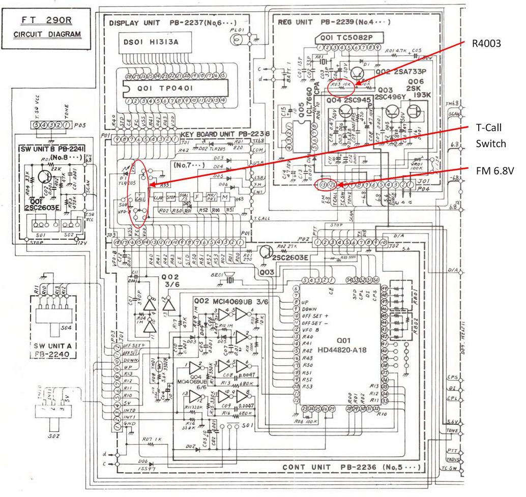
T-Call switch connections and FM 6.8V connection

As with the other installations of this board described on this site, the LED annunciator output is used to switch on an NPN transistor which grounds a Piezzo buzzer enabling the annunciator to be audible in Morse code. In this installation the NPN transistor, its base resistor, the buzzer, the opto isolator and its current limiting resistor are assembled ‘dead bug’ style into a small insulated cluster which tucks almost between two circuit boards and allows short wiring between it and the CTCSS board.

Connection of the tone board’s output caused some difficulty. The usual practice is to inject the tone after the deviation adjustment control (VR2002). This avoids attenuation of the low frequency CTCSS tones by the microphone amplifier filters and allows independent adjustment of deviation and CTCSS tone level. Unfortunately, the Yaesu documentation available is rather poor. The manual contains some black and white photographs which identify adjustment points, semiconductors and other major components. However, most of the passive components remain unidentified. There are no component designations on either the component or the solder sides of the circuit boards, and the values of various components on the circuit diagram appear to differ from the values given in the component listing. The result is that I found it almost impossible to accurately navigate around the PCB and to know precisely where I was! In the end the best tone insertion point was found by educated trial and error but I must confess that I could not say exactly where on the circuit diagram that point is. The best I can say is that I believe it to be just after the deviation adjustment potentiometer and that the point shown here does work.
The result is a very neat, unobstrusive installation which allows easy selection of CTCSS tones from the front panel with audible identification of the selected tone whenever the rig is switched on and repeater mode is selected. The process of installation is not unduly difficult, requiring only the ability to solder well and deal with through-hole type components. Other than lifting one end of a resistor from the PCB (R4003), no permanent alterations are made to the radio so that it could easily be returned to its original state if required. There must be many FT290Rs which could be brought out of retirement and provide useful service with this conversion.
Bill of Materials
- G8TMV tone board (http://www.tuckley.org/ctcss/)
- NPN transistor (PN2222, BC547 or similar)
- Piezzo buzzer –must be rated to work below 6.8V e.g. Pro-Signal ABI-009-RC (CPC or Farnell) Pro Signal ABI-009-RC Buzzer Datasheet
- Resistors 220R and 270R 0.25W or 0.125W
- 2x 1N4148 Diodes
- Opto-coupler (4pin e.g. Sharp PC817 series) Sharp PC817 Opto-coupler Datasheet
- Thin multi-strand wire in various colours. (1mm diam.)
- Thin (2mm diam.) screened audio cable
- Heat-shrink tubing
- Laminating pouch
G8TMV Board Update
Please note that Colin has since released his Rev. 5 board which is slightly smaller and also includes a ‘down’ button. This would enable the tone to be selected by scrolling up or down the list, but would require an extra switch. The new rev. 5 board can be used exactly as described here by using only the ‘up’ button.
Installation instructions
1. Unscrew the telescopic aerial. Remove the top and bottom panels by removing 2 crosshead screws at the rear ( top panel) and open the slide lock (bottom panel). It may also be a good idea to unsolder the speaker lead from the speaker. Remove the battery case. Unscrew and remove the two aluminium side strips. Use a 10mm socket to remove the front studs. Remove the 4 crosshead countersunk screws holding the plastic front panel to the chassis sides and ease the front panel forwards slightly.
2. With the rig upside down and the battery case removed, the regulator board can now be eased away upwards. The regulator board is the one closest to the battery container and carries the lithium back-up battery and a fuse. In the rig shown, there were dried out remnants of tape and adhesive around this area which were cleaned off. Also the back-up battery had expired (exploded) and was replaced during this installation with a coin cell case soldered to the PCB to ease future replacement.
3. 6.8Volt Supply: Locate the connector at the top edge of the board and solder a wire to the land shown below. This is the 6.8 volt FM supply. When the PCB is back in place this wire will pass between the top edge of the PCB and the battery tray.
4. Tone Select: Unsolder the end of R4003 and lift it from the PCB, as shown below. From the component side of the board insert and solder a wire to the land vacated by R4003. This is the connection to the T-Call button. I slipped a short length of heatshrink sleeve over R4003 to isolate it.

The regulator board can now be replaced in its locating slots.
5. PTT: With the rig still bottom side up, unsolder the ground strap from the top left corner of the keyboard PCB. This is the board closest to the front panel. Ease the front panel away to expose the wiring at the back of the microphone socket. Solder a wire to the terminal third down on the outer aspect of the socket. The existing wire is white/green in the two examples I have seen.

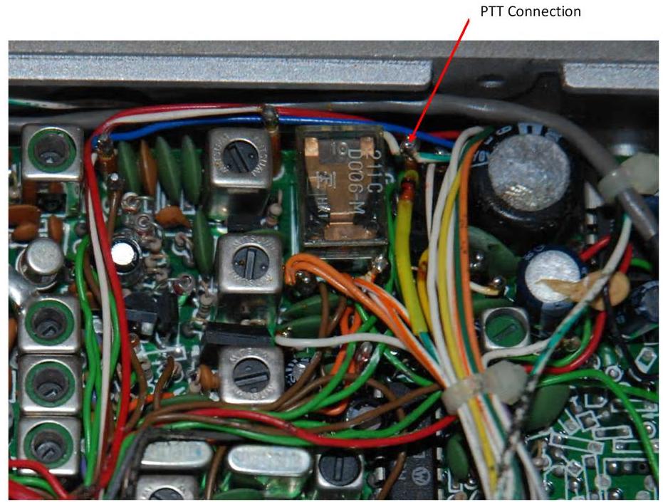
There are two alternatives to soldering to the rear of the microphone socket. The first is to connect a wire to the pin next to the relay (see below) and run the wire forwards and then feed it through to the underside of the radio. The other potential connection point is the center pin of the ‘Standby’ jack on the left hand side of the rig. If there is any doubt, check for direct continuity with the socket pin shown above.

6. Repeater Mode Selection: Turn the radio top side upppermost. Identify the 12 way connector on the top right hand side of the control unit PCB just in front of the screening enclosure. The left hand two connections (pins 11 and 12) are what we are interested in. Ease the board forwards away from the screened enclosure to enable access to the soldered connections on the PCB. Take the two 1N4148 diodes and trim and tin the cathode (bar end) leads at about 6mm. Carefully solder each diode to the lands corresponding to pins 11 and 12 of the connector. The other ends of the diodes (anodes) are soldered together and to another length of connecting wire. This connects to the opto-isolator LED (pin 2) via a 270R resistor. Apply some heatshrink sleeving to cover the diodes and the junction with the wire and dress the assembly so that it sits neatly between the control unit PCB and the screened enclosure. Feed the wire between the control PCB and the keyboard PCB, to the underside of the rig.

7. Ground: Offer up the front panel and refit the 4 screws connecting it to the chassis sides. Re-solder the ground strap to the keyboard PCB and solder a wire to the same point. This is the ground connection for the tone board.
8. Tone Output: I used thin audio screened lead (2mm diameter) connected as shown below. Feed the screened lead across the print side of the main PCB and underneath the regulator unit PCB.

9. The tone encoder board now needs to be insulated. I fabricated a pocket by cutting, scoring and folding an envelope made from a 125 micron laminating pouch which was passed, empty, through a hot laminator. Alternatively, suitable plastic could be rescued from the recycling box. Measure and cut out the shape shown below and lightly score the creases to enable the folds to be made accurately. Punch holes to allow for connecting wires to reach the board, the hole in the top edge allows adjustment of the tone output level trimmer.


10. Now build the opto-isolator / buzzer cluster. I started by extending the +ve lead of the buzzer with tinned copper wire. Pins 1 and 4 of the opto-isolator were gently bent so that they could both be attached to this wire, which is then connected to the 6.8V supply wire. Connect buzzer -ve to the transistor collector. Connect the base to the 220R resistor, the other end of which is then wired to the ‘LED’ pad on the tone board. The transistor emitter is wired to ground at the same point as the ground wire to the tone board. Opto-isolator pin 2 connects to the 270R resistor and then to the wire from the two diodes. Opto-isolator pin 3 is wired to the +ve pad on the tone board.
As all these connections are made, slip thin heatshrink sleeving over the joints and shrink it with a hot air gun or hairdryer.

11. The board can now be wired up; screened lead to ‘Out’ and ‘Gnd’, single wires to ‘+ve’, ‘Gnd’, ‘PTT’, ‘But’ and ‘LED’. Remember to thread the wires through the nearest hole in the insulation envelope before soldering to the appropriate pad.
12. The insulated G8TMV board will just fit between the keyboard PCB and the control unit PCB, inserted from the underside of the rig, just next to the mode switch. (See below).

When working properly, put heatshrink sleeving over the buzzer assembly and tuck it between the edges of the control PCB and the keyboard PCB.

Remember to resolder the speaker lead and refit the side, top and bottom case panels.
Testing and Commissioning
- Switch on the rig.
- Set MODE to FM,+ or – repeater offset.
- There should be an audible Morse code character.
- Press the ‘CALL’ button. Another Morse character should be heard. With successive presses of the ‘CALL’ button the CTCSS board will scroll through the 10 available tones. When the tone you wish to use is selected press and hold ‘CALL’ until you hear a beep. That tone is now set as the default tone until deliberately changed.
- Finally, the tone deviation needs to be set by adjustment of the trimpot on the board. Ideally this should be done using a deviation meter to set the tone deviation to 250-300Hz. Alternatively, the pragmatic approach is to slowly advance the injection setting to that which reliably opens repeaters.
References:
Sharp PC817 Opto-coupler Datasheet
Pro Signal ABI-009-RC Buzzer Datasheet
G4KQK
November 2016

Hello,
To clarify with R4003 are you completely discounting it from the board. or are you just soldering a extra wire to it?
Best regards,
2E0EEJ
Hi Thomas,
Thanks for the message. I simply unsoldered one end of R4003, as shown on the photograph, and lifted that end of the resistor from the PCB. The other end was left attached to the board for no reason other than to leave the option of reversing the conversion if needed in the future. The tone select wire was connected to the PCB in the hole vacated by R4003. No new connection was made to R4003 and it was sleeved in heatshrink only to prevent accidental shorting to other components.
Hope this helps. Good luck with the conversion.
Nick. G4KQK
I have another question regarding the opto coupler. Do I need it or not? I do not intend to put in a Buzzer and trying to keep the price to a minimum.
de 2E0EEJ, Tom
Hi Tom, Apologies for the delay in replying. I have been away for a few days this week.
The purpose of the optocoupler was to allow the encoder board to be powered only when the rig was switched to repeater mode. It had nothing to do with using a buzzer. If you are not wanting to install a buzzer, you could dispense with the NPN transistor and its base resistor. You could omit the optocoupler but the encoder would then need to be powered all the time -even in simplex mode- which is not ideal. Optocoupler choice should not be critical and they are available for pence.
Hope this helps
73 Nick G4KQK
I have got to step 8. My main PCB seems to be different I can not find were to put the input in.
Thanks for the super well written documentation for this mod, it is incredibly helpful! I have a question – do you have any thoughts on how to do this mod and retain listen on input?
Thanks, Jerry G4EPC
Hi Jerry, To be honest, I was not aware of the ability to listen on the input on the 290 Mk1. There is a modification published on the web which appears to use the ‘call’ button. If this mod has already been done, then I guess you could install another small push switch, perhaps on the rear panel for CTCSS tone selection. Personally, I was keen not to permanently alter what was otherwise a mint example of the radio.
73
Nick G4KQK
Thanks for the reply Nick, on reflection I decided to remove the listen on input mod and now have the encoder all working in my 290. I didnt use a buzzer but have a nice blue led installed near the s-meter instead and it seems to be working well. Thanks again! Jerry, G4EPC
Hello Tom, I wonder if you could email some photographs of your board and I will do my best to help.
73
Nick G4KQK
Hi,
I am having problems trying to print the FT290r modification instructions. Any ideas?
Chris G4BYZ
Hello Chris,
Thanks for the interest. On my old machine running XP and office 2007, highlighting the instructions, then right clicking ‘copy’ , then opening a word document and pasting into it works reasonably well for me.
73
Nick G4KQK
Thanks for your reply Nick,
You learn something every day, it works fine.
73
Chris G4BYZ
Good evening Nick,
Down entirely to my negligence I omitted the 270r resistor on the opt isolator circuit. This resulted in excessive current drain on the 6.8v supply.
I believe that this has damaged the supply circuit as now the full 12v appears on the 6.8v pins. This has had a catastrophic effect on the radio and I believe I have damaged it beyond repair. A great pity as it was working so well. Do you have any advice?
Let this be a warning to others !!!
Thanks for a great site. I will probably try again with another 290r if I can get hold of one.
Regards Chris G4BYZ
Hello Nick,
Having resurrected the FT290r from the dead with your help, it is now working extremely well and the CTCSS mod is excellent.
I have now acquired a FT790r and wonder if you have any experience in fitting the CTCSS module to this 70cm rig.
Regards Chris G4BYZ
Hi Chris,
Apologies for the delayed reply- I was away last week. Unfortunately , I don’t have any experience with the 790. However looking at the circuit diagram, there are similarities. The ‘Tone button appears to have a similar function and could be isolated in the same manner by lifting R3013 on the AF board (instead of R4003 in the 290). The FM 6.8V supply would need to be picked up -possibly from J04 on the main board.
The switching arrangement for repeater mode appears to different. Rather than pulling lines to ground as in the 290, the lines appear to be pulled high to 6.8 volts. This would need the connections for powering the LED side of the optocoupler to be changed accordingly. The tone injection point would need to be worked out- VR1007 appears to be the deviation pot, so a point soon after that would need to be found by trial and error. The PTT line appears to be activated by grounding as in the 290, so that should pose no difficulty.
The other issue will be accommodating the tone board physically. I have not been inside a 790 and therefore cannot comment on where to site the board.
Good luck with the installation. If I can be of help, I will do my best. I shall be interested to hear how you get on. I’m sure there is no fundamental reason as to why it should not be possible.
73
Nick
Hello Nick,
I just thought I would update you on the FT 790 modifications.
The first consideration was the location of the board and I made the decision to mount it outside the casing in a small plastic box. It is very cramped inside the radio and as it is in such good unmolested condition I did not want to start too much surgery.
Because of the varying frequency shifts on the 70cm repeaters I decided to use the Memory Split function in order to achieve the various shifts.
The PTT was taken from the Standby Socket as used on the 290.
I located the wiper for the FM deviation adjustment VR1007 and connected the code output to this.
It all seems to work very well and I have had some good reports. I have not needed to make any adjustments to the deviation level.
Thanks for all your help, I am now looking for an FT221 so if anyone has one for disposal I would like to hear from them.
Regards
Chris G4BYZ
Hi Chris,
Sorry for the delay in replying (once again!),
Very pleased to hear of your success.
From time to time I find myself tempted to buy an FT-221 but have so far managed to resist!
73 Nick G4KQK
Hello Nick,
Since the last message I have acquired an FT221R and completed restoration including fitting the CTCSS board.
It has a Mutek rf amplifier and works very well.
I am now working on a Kenwood/Trio TS 700G which was complete and working but in filthy condition inside and out.
I have sorted out cleaning and minor problems and now get good reports. Just fitting CTCSS to that.
Probably quite mad as I have a FT897 which give 2m and 70cm plus HF with all the bells and whistles, Still it is so easy to use I do like the challenge of the older equipment including the FT101E which I use for HF.
73Chris G4BYZ
Hi there – Just fitted the rev 5 board to my FT290r and it seems fine. I did a little more detective work on the tone insertion point and pin 3 of the uPC577H Q2004 works OK. The old 1750Hz tone actually went onto the open collector o/p of that IC which is the mic pre-amp and I tried that first but the level was not high enough from the CTCSS board. Access for the power switching using the offset switching was nigh impossible without major disassembly so I broke into the wires and sleeved the junctions. I didn’t use an opto-coupler but used a 22k resistor and BC212L in a similar fashion to Q4002 on the regulator board to switch power to activate the board. I mounted the LED at the left-hand side of the S-meter. The easiest PTT access was the ‘Stand by’ jack socket. I have located the enveloped board in the space next to the battery box. After a minor problem with one of the red power lines breaking away from its post and disabling the audio amp, it all works fine and I can now access the local repeater.
Hi all useful site. The use of a simplex inhibit is not needed because there are now internet access simplex channels that require a ctcss tone locally the Echolink channel requites 77Hz to access the network and my guess by now there are others. any way thanks for all the info vr 73 petefmt
Just a different way of doing it – I attached the G8TMV board to a lug in the unused TSQL bay and fed the CTCSS tone directly to the floating TSQL board plug. The input is low impedance but, on full output, the tone board does drive a 250Hz deviation. I deadbugged an NE555 as an audio oscillator and drove that directly from the LED output. The bug sits next to the tone board in that bay. I injected the resulting audio into the top of the volume control (series 10uF tantalum and 100k resistor). No mods to the case, morse ident through the speaker and controllable by the AF Gain.
Many ways of tackling this and a great little radio restored into the bargain!
Thanks for the tips John G0GCD